 |
The Open FUSION Toolkit 26.9
An open-source framework for fusion and plasma science and engineering
|
Loading...
Searching...
No Matches
|
The Open FUSION Toolkit 26.9
An open-source framework for fusion and plasma science and engineering
|
In this example we show how to compute equilibria in ITER with H-mode like profiles for the "inverse" case where we have a desired shape, plasma current and pressure, but the required coil currents are unkown.
This example utilizes the mesh built in TokaMaker Meshing Example: Building a mesh for ITER.
To load the TokaMaker python module we need to tell python where to the module is located. This can be done either through the PYTHONPATH environment variable or using within a script using sys.path.append() as below, where we look for the environement variable OFT_ROOTPATH to provide the path to where the OpenFUSIONToolkit is installed (/Applications/OFT on macOS).
We now create a OFT_env instance for execution using two threads and a TokaMaker instance to use for equilibrium calculations. Note at present only a single TokaMaker instance can be used per python kernel, so this command should only be called once in a given Jupyter notebook or python script. In the future this restriction may be relaxed.
#----------------------------------------------
             ____  ____________
            / __ \/ ____/_  __/
           / / / / /_    / /
          / /_/ / __/   / /
          \____/_/     /_/

Base release:        v1.0.0-beta7
Development branch:  release_26_06
Revision id:         978c4b9f

Parallelization Info:
  Not compiled with MPI
  # of OpenMP threads =    2

Linear Algebra backend: native

#----------------------------------------------
Now we load the mesh generated in TokaMaker Meshing Example: Building a mesh for ITER using load_gs_mesh() and setup_mesh. Then we use setup_regions(), passing the conductor and coil dictionaries for the mesh, to define the different region types. Finally, we call setup() to setup the required solver objects. During this call we can specify the desired element order (min=2, max=4) and the toroidal field through F0 = B0*R0, where B0 is the toroidal field at a reference location R0.
**** Loading OFT surface mesh

**** Generating surface grid level  1
  Generating boundary domain linkage
  Mesh statistics:
    Area         =  2.859E+02
    # of points  =    4757
    # of edges   =   14156
    # of cells   =    9400
    # of boundary points =     112
    # of boundary edges  =     112
    # of boundary cells  =     112
  Resolution statistics:
    hmin =  9.924E-03
    hrms =  2.826E-01
    hmax =  8.466E-01
  Surface grounded at vertex     870


**** Creating Lagrange FE space
  Order  =    2
  Minlev =   -1

 Computing flux BC matrix
 Inverting real matrix
   Time =    8.9499999999999996E-004
Like many elongated equilibria, the equilibrium we seek to compute below is vertically unstable. In this case we use the actual ITER Vertical Stability Coil (VSC) in order to help with convergence using the set_coil_vsc() method.
Hard limits on coil currents can be set using set_coil_bounds(). In this case we just the simple and approximate bi-directional limit of 50 MA in each coil.
Bounds are specified using a dictionary of 2 element lists, containing the minimum and maximum bound, where the dictionary key corresponds to the coil names, which are available in mygs.coil_sets
For the inverse case we define a target for the plasma current and the peak plasma pressure, which occurs on the magnetic axis.
In order to constrain the shape of the plasma we can utilize two types of constraints:
Here we define a handful of isoflux points that we want to lie on the LCFS of the target equilibrium. Additionally, we define a single X-point and set it as a saddle constraint as well as adding it to the list of isoflux points.
In general, for a given coil set a given plasma shape cannot be exactly reproduced, which generally yields large amplitude coil currents if no constraint on the coil currents is applied. As a result, it is useful to include regularization terms for the coils to balance minimization of the shape error with the amplitude of current in the coils. In TokaMaker these regularization terms have the general form, where each term corresponds to a set of coil coefficients, target value, and weight. The coil_reg_term() method is provided to aid in defining these terms.
In this case, one regularization term is added for each coil with a single unit coefficient for that coil and target of zero with modest weights. This regularization acts to penalize the amplitude of current in each coil, acting to balance coil current with error in the shape targets. Note that the weight on the VSC virtual coil (#VSC) defined above is set high to prevent interaction with the real VS coil set (see below for further information).
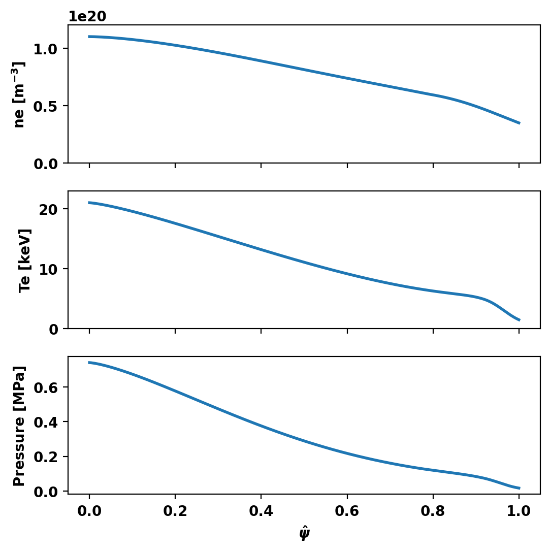
Although TokaMaker has a "default" profile for the F*F' and P' terms this should almost never be used and one should instead choose an appropriate flux function for their application. In this case we use an H-mode-like kinetic profiles parametrized via the OMFIT function Hmode_profiles() (see note at top). Within TokaMaker these profiles are represented as piecewise linear functions, which can be set up using the dictionary approach shown below.
Using the OMFIT Hmode_profiles() profile parametrization function, we can specify ITER-like H-mode profiles. See Figs. 18 and 19 for these \(n_e\) and \(T_e\) profiles: https://iopscience.iop.org/article/10.1088/0029-5515/48/7/075005/pdf
For pressure, we are assuming a quasineutral and isothermal plasma, (i.e. ne = ni, Te = Ti), however this assumption is not usually valid in the core and separate ion profiles will need to be specified.
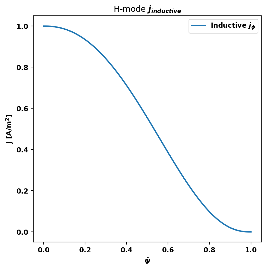
Using the OMFIT Hmode_profiles() profile parametrization function, we can specify an inductive, L-mode-like \(j_{\phi}\) profile. See Fig. 7 for a reference \(j_{total}\) profile including the bootstrap contribution: https://iopscience.iop.org/article/10.1088/0029-5515/48/7/075005/pdf
This \(j_{inductive}\) profile was generated by hand such that the sum of \(j_{inductive}\) and the boostrap current profile ( \(j_{bootstrap}\)) calculated by the Sauter formula approximately equal the high fidelity \(j_{total}\) profile in Fig. 7. Achieving this may require referencing a published \(j_{total}\) profile which was calculated via transport simulations in similar conditions to your goal TokaMaker equilibrium, some iteration by hand, or a combination of the two.
We can now compute a free-boundary equilibrium using these constraints. Note that before running a calculation for the first time we must initialize the flux function \(\psi\), which can be done using init_psi(). This subroutine initializes the flux using the specified Ip_target from above, which is evenly distributed over the entire plasma region or only with a boundary defined using a center point (R,Z), minor radius (a), and elongation and triangularity. Coil currents are also initialized at this point using the constraints above and this uniform plasma current initialization.
solve() is then called to compute a self-consitent Grad-Shafranov equilibrium. If the result variable (err_flag) is zero then the solution has converged to the desired tolerance ( \(10^{-6}\) by default).
Starting non-linear GS solver
     1  5.6716E+00  1.9463E-01  1.1658E-01  6.4419E+00  5.1954E-01  1.3946E-03
     2  1.1100E+01  1.4953E-01  4.9389E-02  6.4278E+00  5.2259E-01  1.0840E-03
     3  1.2565E+01  1.3895E-01  2.6226E-02  6.4160E+00  5.2500E-01  9.8814E-04
     4  1.3048E+01  1.3574E-01  1.3410E-02  6.4088E+00  5.2672E-01  9.5429E-04
     5  1.3218E+01  1.3466E-01  6.5602E-03  6.4050E+00  5.2781E-01  9.4201E-04
     6  1.3281E+01  1.3428E-01  3.1287E-03  6.4029E+00  5.2865E-01  9.3754E-04
     7  1.3304E+01  1.3414E-01  1.4785E-03  6.4019E+00  5.2919E-01  9.3592E-04
     8  1.3312E+01  1.3409E-01  7.0251E-04  6.4014E+00  5.2953E-01  9.3534E-04
     9  1.3315E+01  1.3407E-01  3.4067E-04  6.4012E+00  5.2974E-01  9.3513E-04
    10  1.3316E+01  1.3407E-01  1.7105E-04  6.4011E+00  5.2987E-01  9.3504E-04
    11  1.3317E+01  1.3406E-01  8.9821E-05  6.4010E+00  5.2996E-01  9.3501E-04
    12  1.3317E+01  1.3406E-01  4.9401E-05  6.4010E+00  5.3001E-01  9.3499E-04
    13  1.3317E+01  1.3406E-01  2.8264E-05  6.4010E+00  5.3004E-01  9.3497E-04
    14  1.3317E+01  1.3406E-01  1.6644E-05  6.4010E+00  5.3006E-01  9.3497E-04
    15  1.3317E+01  1.3406E-01  9.9878E-06  6.4010E+00  5.3007E-01  9.3496E-04
    16  1.3317E+01  1.3406E-01  6.0637E-06  6.4010E+00  5.3008E-01  9.3496E-04
    17  1.3317E+01  1.3406E-01  3.7070E-06  6.4010E+00  5.3008E-01  9.3495E-04
    18  1.3317E+01  1.3406E-01  2.2756E-06  6.4010E+00  5.3009E-01  9.3495E-04
    19  1.3317E+01  1.3406E-01  1.4003E-06  6.4009E+00  5.3009E-01  9.3495E-04
    20  1.3317E+01  1.3406E-01  8.6304E-07  6.4009E+00  5.3009E-01  9.3495E-04
 Timing:   9.8389999999199063E-002
   Source:     3.1312999781221151E-002
   Solve:      3.2395000045653433E-002
   Boundary:   3.8310001837089658E-003
   Other:      3.0850999988615513E-002
solve_with_bootstrap() is now called to compute a self-consistent Grad-Shafranov equilibrium that includes non-inductive current (the bootstrap current). Inclusion of bootstrap current effects is essential for H-mode equilibrium stability. If the result variable (err_flag) is zero then the solution has converged to the desired tolerance ( \(10^{-6}\) by default).
 >>> Matching input core j_phi with G-S solution

 >>> Finding optimal j_phi scale factor

--- Checking scale_j0 = 1.0000 ---
   Input j_0:  9.5972e+05
   Output j_0: 1.0361e+06
   Mismatch:  7.371%

--- Checking scale_j0 = 1.2000 ---
   Input j_0:  1.1498e+06
   Output j_0: 1.0968e+06
   Mismatch:  4.829%
--- Optimization Iteration 1 ---

--- Checking scale_j0 = 1.1181 ---
   Input j_0:  1.0719e+06
   Output j_0: 1.0737e+06
   Mismatch:  0.159%
Converged! Optimal scale factor: 1.1181

 >>> Finding optimal Ip scale factor

--- Checking scale_Ip = 1.0000 ---
   Input Ip target:  1.3000e+01
   Trial Ip target:  1.3000e+01
   Output Ip: 1.3000e+01
   Mismatch:  0.0001%

 >>> Iterating on H-mode equilibrium solution
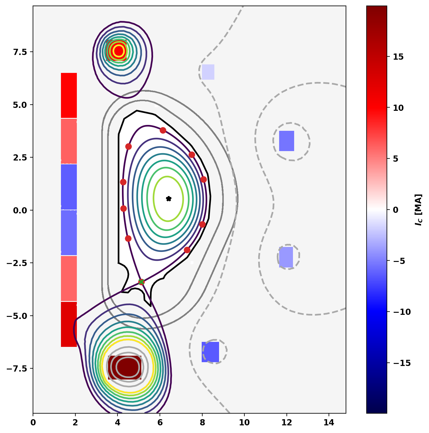
Flux surfaces of the computed equilibrium can be plotted using the plot_psi() method. The additional plotting methods plot_machine() and plot_constraints() are also used to show context and other information. Each method has a large number of optional arguments for formatting and other options.
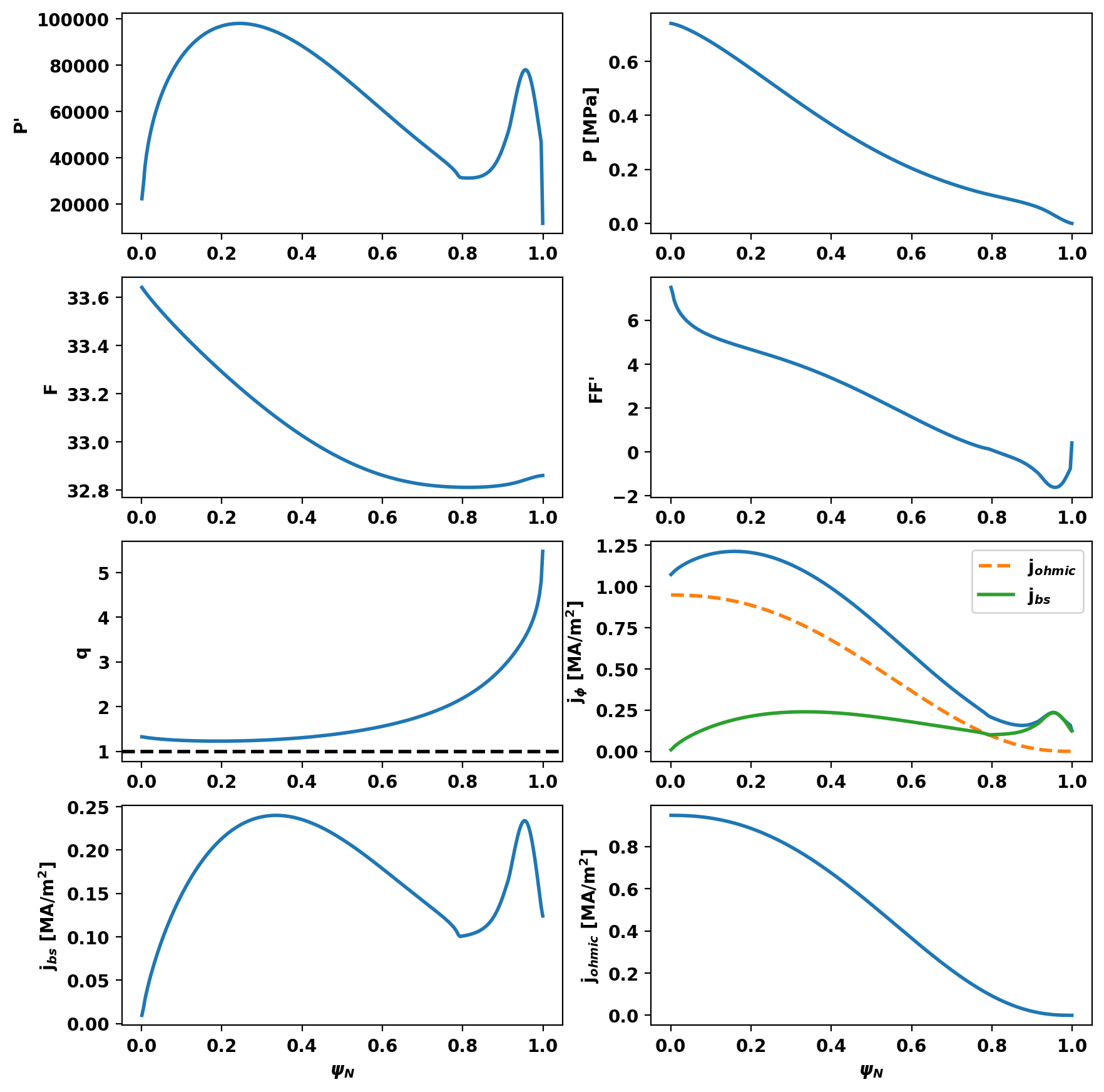
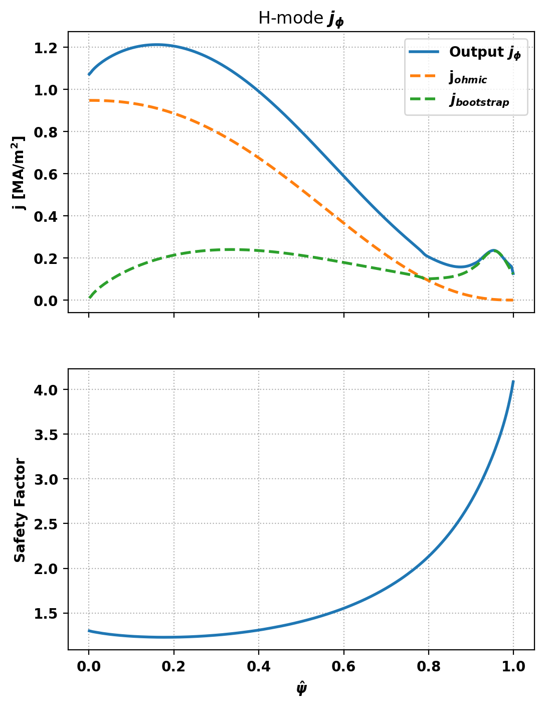
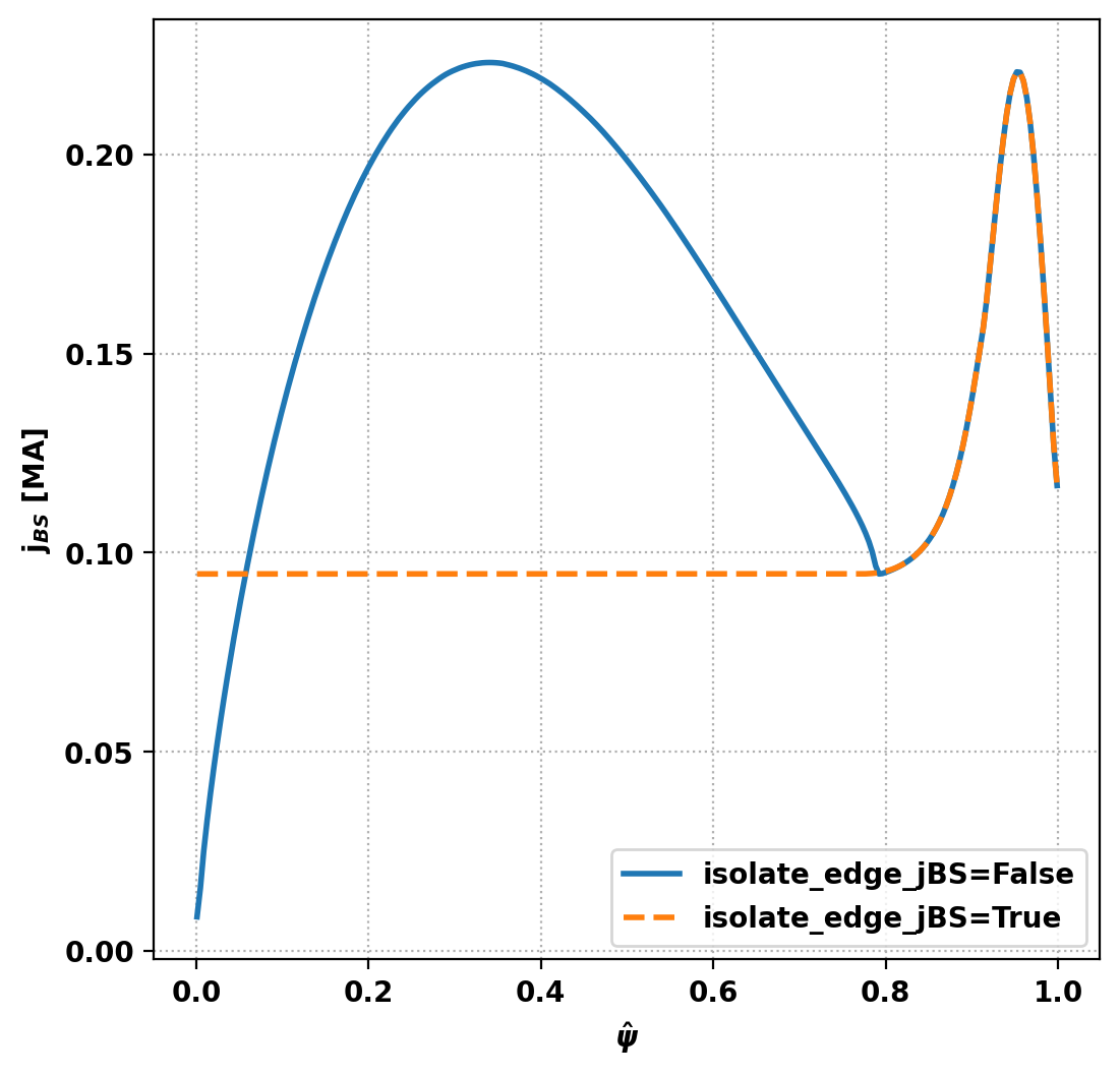
There is a subtle reverse shear region visiible in the core j \(_\phi\) and safety factor profiles, which is resulting from the sum of our inductive profile and the Sauter calculated j \(_{bootstrap}\) profile together providing an excess of current. We can adjust the core j \(_\phi\) (and therefore safety factor) profile to our desired shape by setting isolate_edge_jBS=True in our "solve_with_bootstrap()" call. Now, the edge bootstrap spike will be retained from the Sauter prediction, but the core j \(_\phi\) profile inside the edge j \(_{bootstrap}\) spike will simply be our specified inductive_jphi.
 >>> Matching input core j_phi with G-S solution

 >>> Finding optimal j_phi scale factor

--- Checking scale_j0 = 1.0000 ---
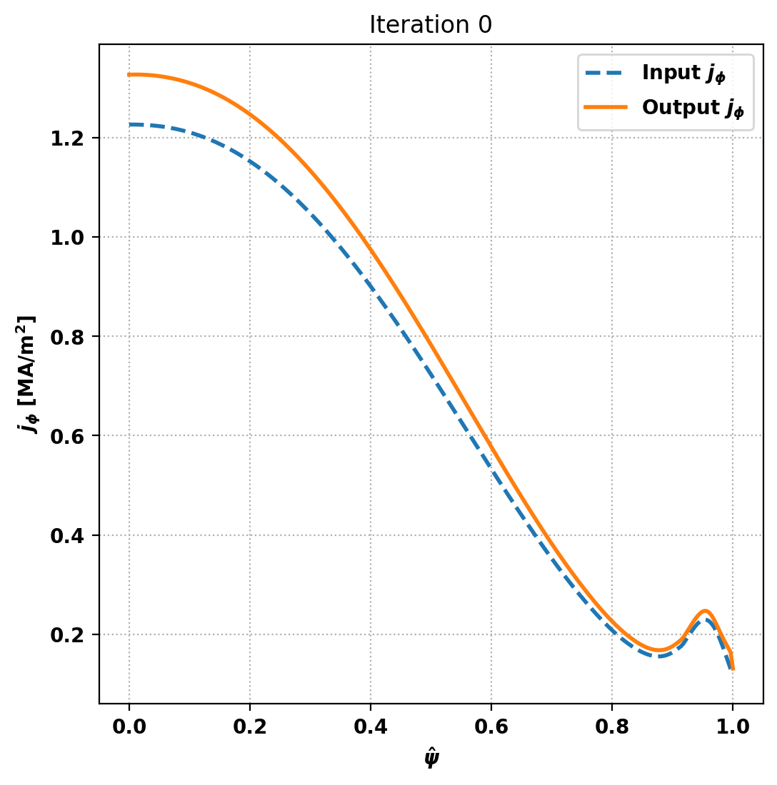
   Input j_0:  1.2266e+06
   Output j_0: 1.3270e+06
   Mismatch:  7.563%

--- Checking scale_j0 = 1.2000 ---
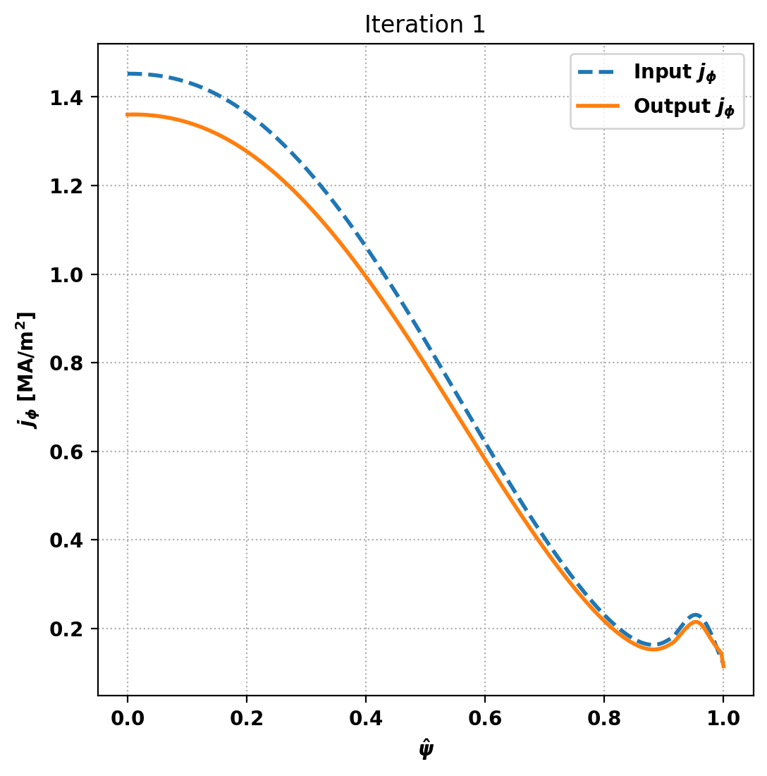
   Input j_0:  1.4526e+06
   Output j_0: 1.3603e+06
   Mismatch:  6.790%
--- Optimization Iteration 1 ---

--- Checking scale_j0 = 1.1041 ---
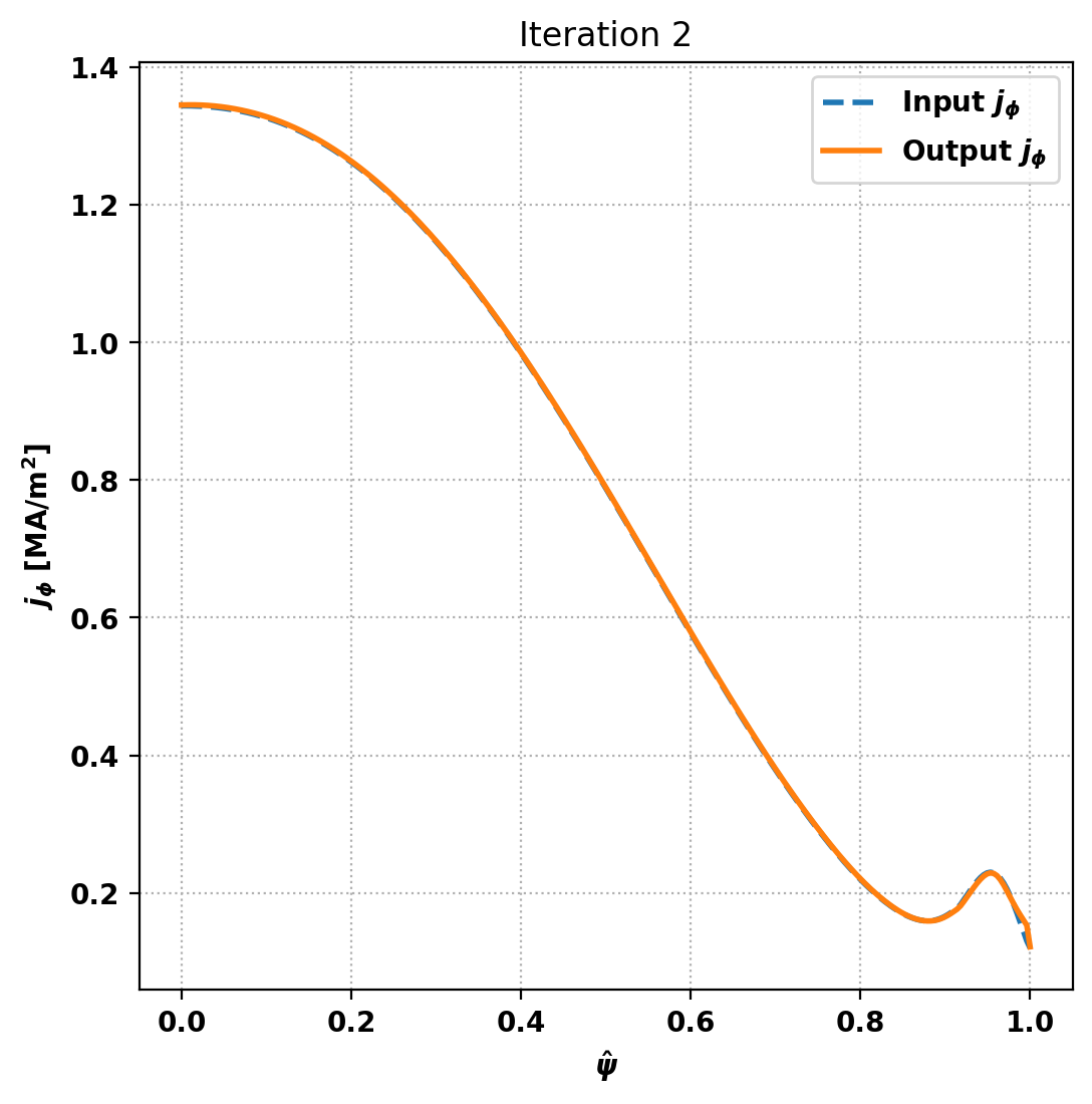
   Input j_0:  1.3443e+06
   Output j_0: 1.3454e+06
   Mismatch:  0.081%
Converged! Optimal scale factor: 1.1041

 >>> Finding optimal Ip scale factor

--- Checking scale_Ip = 1.0000 ---
   Input Ip target:  1.3000e+01
   Trial Ip target:  1.3000e+01
   Output Ip: 1.3000e+01
   Mismatch:  0.0000%

 >>> Iterating on H-mode equilibrium solution
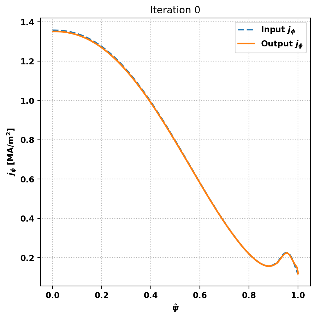
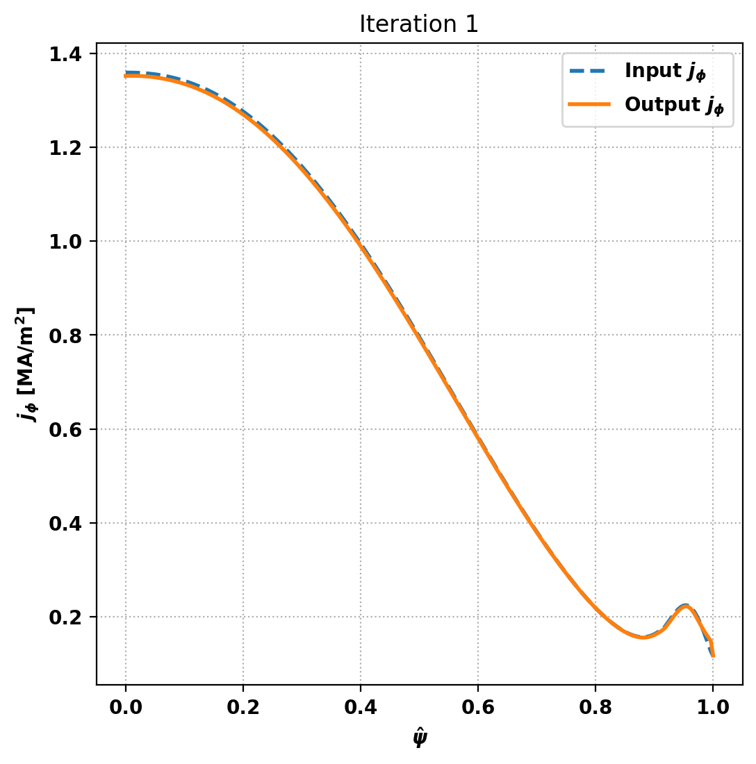
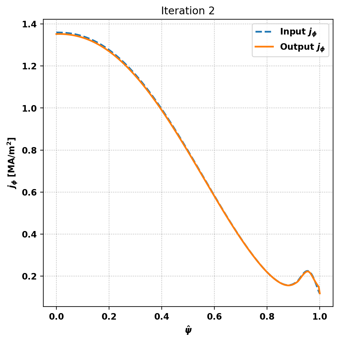
Function 'solve_with_bootstrap' took 12.1883 seconds to execute.
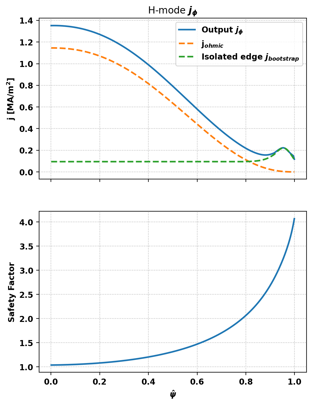
Setting isolate_edge_jBS=True has isolated the edge j \(_{bootstrap}\) spike, meaning that our specified inductive_jphi will functionally be the total j \(_{\phi}\) inside of the splice location, simplifying user control of the core profile shape. The splice is automatically set to occur at the minimum of j \(_{bootstrap}\) in between \(\psi_N\) = 0.5 and the peak of the edge j \(_{bootstrap}\) spike. We can compare the two options as follows:
Basic parameters can be displayed using the print_info() method. For access to these quantities as variables instead the get_stats() can be used.
The final coil currents can also be retrieved using the get_coil_currents() method, which are all within the approximate coil limits imposed above.
Equilibrium Statistics:
  Topology                =   Diverted
  Toroidal Current [A]    =    1.3000E+07
  Current Centroid [m]    =    6.283  0.517
  Magnetic Axis [m]       =    6.412  0.531
  Elongation              =    1.869 (U:  1.745, L:  1.993)
  Triangularity           =    0.472 (U:  0.394, L:  0.550)
  Plasma Volume [m^3]     =   813.752
  q_0, q_95               =    1.039  3.438
  Plasma Pressure [Pa]    =   Axis:  7.3997E+05, Peak:  7.3997E+05
  Stored Energy [J]       =    3.1742E+08
  <Beta_pol> [%]          =   79.8670
  <Beta_tor> [%]          =    2.3435
  <Beta_n>   [%]          =    1.8848
  Diamagnetic flux [Wb]   =    5.0407E-01
  Toroidal flux [Wb]      =    1.1974E+02
  l_i                     =    1.0847

Coil Currents [MA]:
  CS3U:           10.54
  CS2U:            6.97
  CS1U:           -6.83
  CS1L:           -5.88
  CS2L:            7.14
  CS3L:           12.54
  PF1:             9.92
  PF2:            -1.46
  PF3:            -5.53
  PF4:            -4.17
  PF5:            -6.07
  PF6:            19.36
  VS:              0.02
 1.17.0